
Fugitive gas emissions and cylinder leaks present severe safety hazards on the facility floor. They compromise gas purity and result in significant financial losses for industrial and medical operations. Facility managers and procurement engineers must select valve mechanisms that guarantee precise gas regulation. These components prevent atmospheric ingress and maintain strict regulatory compliance under high-pressure conditions. Relying on standard fittings often falls short in demanding environments where vibration and thermal shock are constant threats. Mitigating these risks requires moving beyond basic hardware to evaluate specific engineering features. You must analyze everything from backseating mechanisms to residual pressure devices. Understanding how manual controls dictate leak prevention efficacy dictates your operational success. Selecting the right components ensures long-term system integrity, prevents catastrophic blowouts, and protects personnel from exposure to hazardous materials.
Manual operation via a handle wheel valve provides critical tactile feedback and precise flow regulation to a safe working level, which is essential for immediate leak mitigation and safe system operation.
Integrating a cylinder valve with residual pressure device (RPV) prevents backflow by retaining a small volume of gas, eliminating the risk of internal cylinder contamination and corrosion.
Procuring a TPED certified gas cylinder valve or a CGA V9 cylinder valve is a non-negotiable baseline for ensuring operational legality, standardized safety margins, and liability protection.
Effective valve selection requires a rigorous trade-off analysis between upfront component costs and the long-term reduction of maintenance overhead, gas loss, and catastrophic failure risks.
Cylinder valves operate under extreme mechanical and environmental stress. Identifying where these components fail is the first step in establishing robust leak control. Gland leakage represents a primary vulnerability when valves remain in the open position. The packing gland acts as the main dynamic seal. System pressure constantly forces gas against this barrier. Over time, friction from repeated operation degrades the packing material, allowing trace gases to escape into the atmosphere. You will often see this manifest as a slow pressure drop on static lines. The specific type of packing material matters heavily here. PTFE (Teflon) is common but can cold-flow under continuous pressure. PCTFE (Kel-F) offers better structural integrity for high-pressure applications.
Thread degradation presents another severe risk. The lower valve stem interacts directly with the wetted gas stream. When handling reactive or corrosive gases, these internal threads suffer chemical attacks. This exposure leads to galling, stripping, and eventual mechanical failure. The connection points also endure heavy physical abuse. The inlet connection joins the cylinder to the valve, typically using a National Gas Taper (NGT) thread. This thread relies on a metal-to-metal interference fit, often supplemented with PTFE tape or specialized thread sealants. If an operator applies the wrong sealant, it can act as a lubricant, causing over-insertion and splitting the cylinder neck. The outlet connection links the valve to the regulator. Both points face extreme torque and lateral stress during cylinder transport and installation. A compromised thread at either junction creates an immediate high-pressure leak path.
The pressure relief valve serves as the ultimate failsafe. Its role is venting excess gas rapidly if internal pressure exceeds safe design limits during a fire or thermal event. The burst disc mechanism consists of a thin metal membrane engineered to rupture at a specific pressure, usually backed by a fusible plug that melts at a specific temperature. However, a poorly designed or degraded pressure relief device can act as a vulnerability point itself. Burst discs can suffer from metal fatigue due to pressure cycling. Spring-loaded relief valves may fail to reseat properly after a minor pressure spike, resulting in a continuous, uncontrolled leak.
To systematically identify these vulnerabilities on the floor, maintenance teams should follow a strict inspection sequence:
Inspect the valve inlet threads for signs of galling or deformation before installation.
Examine the packing nut for proper torque, ensuring it has not backed off due to thermal cycling.
Check the pressure relief device for any signs of extrusion, corrosion, or tampering.
Verify the outlet connection surface is free of deep scratches or dents that could compromise the regulator O-ring seal.
Achieving high-integrity gas containment requires strict adherence to baseline mechanical requirements. Material compatibility dictates the core safety of the entire assembly. You must match the valve material precisely to the gas application. Corrosive gases require high-grade stainless steel or specialized alloys to resist chemical degradation. Inert gases function reliably with standard brass components. Reactive gases demand highly inert internal surfaces to prevent dangerous chemical interactions. Refrigerant gases require specific elastomeric seals that resist swelling or cracking when exposed to synthetic compounds.
Success criteria also depend heavily on cycle life and wear resistance. Industrial valves must withstand thousands of open-and-close cycles without losing seal integrity. Engineers measure this through rigorous endurance testing, often pushing valves to 2,000 or 5,000 cycles under full working pressure. The ability of the pressure relief valve to function reliably during extreme temperature fluctuations is equally important. Cold environments harden elastomeric seals, making them brittle. Hot environments increase internal cylinder pressure, testing the structural limits of the burst disc or spring mechanism. High-quality valves maintain their performance metrics across these temperature extremes.
| Gas Category | Recommended Valve Material | Primary Seal Requirement | Common Applications |
|---|---|---|---|
| Inert Gases (Argon, Nitrogen) | Forged Brass | PTFE / Nylon | Welding, Purging, Blanketing |
| Corrosive Gases (Chlorine, HCl) | 316L Stainless Steel / Monel | PCTFE / Hastelloy | Chemical Processing, Semiconductor |
| Refrigerant Gases (R-134a, R-410A) | Brass with Specialized Plating | Neoprene / Specific Elastomers | HVAC, Industrial Cooling |
| High-Purity Oxygen | Brass / Monel (Oxygen Cleaned) | Ignition-Resistant Polymers | Medical, Aerospace |
Manual operation remains a cornerstone of safe gas handling. A well-designed handle wheel gas cylinder valve enables precise manual control over the gas stream. Operators can regulate gas flow to a safe, stable working level before fully engaging the system. This gradual introduction of pressure protects downstream regulators from destructive pressure surges. The ergonomic design of the handwheel allows operators to make micro-adjustments easily, even while wearing heavy protective leather or nitrile gloves. The materials used for the handwheel itself matter. Aluminum handwheels are lightweight but can melt in a fire. Brass or steel handwheels offer better fire resistance. A lobed design provides better grip for gloved hands compared to a smooth knurled edge.
Tactile feedback is a primary safety feature of manual valves. Experienced operators rely on the physical sensation of the valve seating to confirm a positive shut-off. You feel the exact moment the internal stem seals against the orifice. This physical confirmation prevents reliance solely on secondary pressure gauges, which can malfunction or display delayed readings. Immediate tactile response allows for rapid leak mitigation during emergency shutdowns.
Engineered handle designs actively mitigate the risks of overtightening. Applying excessive torque is a leading cause of valve failure. When operators force a valve closed, they crush the internal stem and damage the soft seating materials. This creates permanent leak paths that no amount of tightening can fix. Modern handwheels are sized to limit the maximum torque an average operator can apply by hand. This physical limitation protects the internal components and ensures the valve maintains its seal integrity over thousands of cycles.
Backseating is a mechanical feature designed to isolate the packing gland from system pressure. You activate this feature by turning the handwheel until the valve is in the fully open position. As the lower stem rises to allow gas flow, the upper stem engages a secondary sealing surface against the internal bonnet. This metal-to-metal or metal-to-polymer seal physically blocks the high-pressure gas from reaching the primary packing area.
This mechanical process drastically reduces continuous wear on primary seals. In facilities where gases flow continuously for days or weeks, exposing the packing gland to constant high pressure accelerates degradation. Backseating removes this stress entirely. It shifts the containment burden to a static, robust internal seal. Operators must be trained to open these valves completely to engage the backseat. Leaving a valve partially open defeats this feature, leaving the packing gland vulnerable to continuous pressure and eventual leakage.
| Design Type | Mechanism | Leak Prevention Benefit | Best Use Case |
|---|---|---|---|
| One-Piece Stem | Stem rotates directly against the seat during closure. | Fewer internal components, reducing static leak paths. | Low-pressure, inert gas applications. |
| Two-Piece Stem | Upper stem rotates; lower spindle moves linearly without rotation. | Prevents galling and seat tearing, extending seal life. | High-pressure, high-cycle industrial applications. |
| Diaphragm Packless | Metal diaphragms isolate the gas stream from the stem threads. | Eliminates gland leakage entirely. | Ultra-high purity and highly toxic gases. |
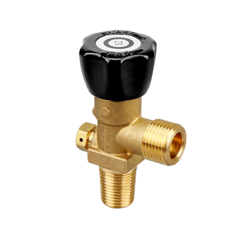
Maintaining internal cylinder purity is just as important as preventing external leaks. A cylinder valve with residual pressure device (RPV) addresses this challenge directly. An RPV functions similarly to a standard valve during normal operation, allowing full flow to the regulator. However, as the cylinder empties, the RPV mechanism activates. It automatically closes before the internal pressure drops to zero, typically retaining a small, specific volume of gas at around 3 to 5 bar (45 to 75 psi).
This retained gas maintains a positive pressure baseline inside the cylinder. It physically prevents the internal environment from reaching a zero-pressure state. By maintaining positive pressure, the RPV eliminates atmospheric ingress. Ambient air, moisture, and airborne contaminants cannot push their way into the cylinder. This mechanism directly prevents internal cylinder corrosion, which is often caused by moisture reacting with residual gas traces to form weak acids.
The use of RPVs correlates strongly with extended cylinder longevity. Cylinders equipped with these devices require less frequent internal cleaning, and hydro-testing failures drop significantly. Furthermore, RPVs preserve the integrity of high-purity gases. When a cylinder returns to the filling plant with its positive pressure intact, the supplier knows the interior remains uncontaminated. This reduces the time and resources required to purge, bake, and prep the cylinder for its next fill.
Valve Integrated Pressure Regulators (VIPR) represent a significant structural advancement in gas containment. A VIPR consolidates the traditional cylinder valve and the external pressure regulator into a single, unified brass or steel forging. This structural advantage dramatically reduces the total number of potential leak paths. By eliminating the threaded connection between a separate valve and regulator, you remove one of the most common sites for high-pressure leaks on the facility floor.
Evaluating VIPRs requires understanding specific conceptual trade-offs. On the positive side, VIPRs offer unmatched operational convenience and enhanced safety. Operators handle fewer loose components, and the integrated gauge provides immediate pressure readings. The preset regulation minimizes the risk of downstream over-pressurization. However, this integration increases mechanical complexity. If the regulator component fails, you cannot simply swap it out on the floor; the entire VIPR unit often requires specialized servicing or replacement. Facilities must weigh the reduction in leak paths against the higher replacement costs of these integrated units.
| Feature | VIPR (Integrated System) | Traditional Valve + External Regulator |
|---|---|---|
| Leak Paths | Minimized (no external high-pressure connection). | Multiple (cylinder to valve, valve to regulator). |
| Handling | Ergonomic, built-in guards protect components. | Requires careful handling of exposed regulator. |
| Maintenance | Requires specialized servicing or full unit replacement. | Regulators can be swapped out quickly on the floor. |
| Application | Medical oxygen, portable welding kits. | Stationary industrial manifolds, high-flow systems. |
Regulatory compliance is the foundation of industrial safety. The CGA V9 standard dictates strict performance, design, and qualification testing requirements for gas cylinder valves in North America. To meet this standard, valves must pass exhaustive tests, including extreme temperature cycling, hydraulic burst testing, and impact resistance evaluations. These tests simulate the harshest field conditions to ensure the valve will not fail catastrophically under duress.
Adherence to the CGA V9 standard ensures interoperability across different equipment brands and gas suppliers. When you specify a cga v9 cylinder valve, you guarantee that the inlet and outlet threads conform to exact dimensional tolerances. This prevents mismatched connections, which are a primary source of severe leaks. Furthermore, this certification establishes verifiable safety margins for high-pressure containment, giving facility managers confidence in their infrastructure.
For global and European market compliance, the Transportable Pressure Equipment Directive (TPED) sets the legal benchmark. TPED requires rigorous third-party testing and continuous manufacturing audits. It focuses heavily on the safe transport of pressurized gases across public infrastructure. Valves must demonstrate exceptional resistance to vibration, impact, and extreme environmental shifts to earn the Pi (π) mark associated with this directive.
Procuring a tped certified gas cylinder valve directly impacts facility liability and risk management. Insurance underwriters frequently require TPED or equivalent certifications when assessing policies for industrial facilities. Using non-certified equipment voids insurance coverage and exposes the company to severe legal penalties in the event of an accident. TPED certification provides a documented, legally defensible proof of safety that protects both personnel and the corporate entity.
Even the highest-quality valves fail if implemented incorrectly. Specifying mismatched valve materials for specialized applications is a frequent and dangerous error. For example, using standard brass components for corrosive refrigerants or ammonia leads to rapid chemical degradation. The internal seals swell, crack, or dissolve, resulting in massive gas releases. You must verify material compatibility charts before finalizing any procurement decision.
Handling refrigerant gases requires specific safety best practices to prevent mechanical degradation. These gases often experience phase changes from liquid to gas at the valve interface, causing extreme localized temperature drops. This thermal shock can damage standard elastomeric seals. Operators must open these valves slowly to manage the thermal transition and prevent seal blowout. Rapid opening can also cause adiabatic compression in oxygen systems, generating enough heat to ignite particulate matter inside the valve body.
Operator handling errors remain a persistent threat to valve integrity. A common violation is using wrenches, pliers, or unauthorized leverage tools on a Handle Wheel Valve. These tools apply torque far beyond the design limits of the internal stem. This crushes the soft seat, shears the stem threads, and creates permanent mechanical failure. Facilities must enforce strict policies requiring operators to use only manual hand force when operating cylinder valves.
Detecting leaks early prevents minor issues from escalating into catastrophic failures. Standardizing leak detection protocols is essential for maintaining system integrity. The most reliable, evidence-based procedure is the routine bubble test. Operators apply a specialized, non-corrosive leak detection fluid to both the inlet and outlet connections. Even microscopic leaks will cause the fluid to form visible bubbles. This test must be performed every time a cylinder is connected, disconnected, or subjected to severe temperature changes.
To execute a proper bubble test, operators should follow these steps:
Pressurize the system slowly to the normal operating pressure.
Apply the approved leak detection fluid generously around the cylinder neck thread and the regulator connection.
Observe the coated areas for at least 60 seconds, watching for the formation of expanding bubbles.
If bubbles appear, depressurize the system immediately, inspect the sealing surfaces, and retighten to the specified torque before retesting.
Beyond the bubble test, facilities must monitor for unexpected changes in system pressure. A slow pressure drop on a static line often indicates a micro-leak that is not immediately audible. Implement digital pressure monitoring where possible to track these subtle changes over time. Electronic leak detectors also provide advanced monitoring capabilities. Ultrasonic detectors listen for the high-frequency hiss of escaping gas, which is useful in noisy industrial environments where a bubble test might be impractical for overhead piping. Documenting leak test results and pressure drops allows maintenance teams to identify degrading components and replace them before they fail completely.
Audit your current cylinder inventory to verify strict material compatibility between the gas type and the installed valve components.
Implement mandatory, hands-on training for all operators focusing on tactile feedback and the strict prohibition of tools on manual handwheels.
Transition to residual pressure devices (RPVs) for all high-purity and corrosive gas applications to eliminate atmospheric ingress and internal cylinder damage.
Establish and document a standardized bubble test protocol for every cylinder connection and disconnection event on your facility floor.
A: Gland leakage occurs when the internal packing material degrades due to friction and continuous exposure to high system pressure. Opening the valve fully to engage the backseat mechanism isolates the gland from this pressure, significantly reducing wear and preventing leakage.
A: A residual pressure device retains a small volume of gas to maintain positive pressure inside the cylinder. This constant positive pressure physically blocks ambient air and moisture from entering the empty cylinder, which directly prevents internal rust and chemical corrosion.
A: Tactile feedback allows the operator to physically feel the exact moment the valve seats properly against the orifice. This confirms a secure, positive shut-off without overtightening, which can crush internal components and create permanent leak paths.
A: The pressure relief valve is a critical safety failsafe designed to vent excess gas if the cylinder experiences extreme heat or over-pressurization. This rapid venting prevents catastrophic cylinder explosions during fires or severe thermal events.
A: You should perform a bubble test every time you connect a new cylinder to a regulator or piping system. Routine checks during prolonged operational periods also help identify slow, degrading leaks before they become hazardous.
A: No. Using wrenches or pliers applies excessive torque that exceeds the design limits of the valve. This crushes the internal seating surfaces and damages the stem, creating permanent leaks. Always operate handwheels using only manual hand force.


