
In high-pressure gas containment, the margin for error is zero; a compromised valve seal risks catastrophic pressure release, hazardous exposure, or costly gas loss. Procurement and engineering teams frequently oversimplify valve selection, treating all manual valves as commodities. This leads to specifying valves with inadequate sealing architectures for specific gas purities or pressure thresholds, resulting in premature failure and safety compliance violations. Specifying the correct Handle Wheel Valve requires a rigorous understanding of internal sealing mechanics—from packing rings to metal-to-metal pressure seals. This guide breaks down how these valves achieve leak-tight integrity, the criteria for evaluating them, and how to align valve specifications with operational and regulatory requirements.
Seal Architecture Dictates Application: The choice between soft-seat (e.g., Teflon/PTFE) and metal-to-metal seals directly impacts cycle life, gas purity, and pressure tolerance.
Gas-Specific Engineering is Non-Negotiable: Reactive gases require specialized internal mechanisms, such as back-seating features in a high pressure oxygen cylinder valve, to prevent ignition and stem leaks.
Compliance Equals Viability: Specifying a TPED certified gas cylinder valve ensures the component has passed stringent European pressure equipment directives, serving as a baseline for global safety and reliability.
User Error Drives Most Failures: Even the most advanced handle wheel gas cylinder valve will fail if subjected to overtightening, debris contamination on mating surfaces, or improper cleaning procedures.
To evaluate a valve's reliability, buyers must first understand the mechanical components responsible for isolating high-pressure gas from the atmosphere. A standard handle wheel gas cylinder valve relies on a complex interaction of machined surfaces, engineered polymers, and applied mechanical force. The sealing architecture determines how well the unit handles repeated cycling under extreme pressure. When you operate a cylinder in the field, you are relying on precise internal geometry to hold back up to 300 bar (4,350 psi) of stored energy.
The core of any cylinder valve is the lower stem and seat assembly. When you rotate the handwheel clockwise, the threaded stem drives the seat downward against the valve body orifice. The specific design of this interface dictates the valve's performance characteristics and its resistance to wear over thousands of cycles.
Metal-to-metal pressure seals utilize a precision-machined brass or stainless steel tip that mates directly with the metal orifice. This design handles high-purity and high-pressure applications effectively. Metal seals resist chemical degradation and do not outgas contaminants into the gas stream. They require higher closing torque to achieve a positive seal and are highly susceptible to damage from microscopic particulate debris. If a technician wrenches down on a metal-to-metal seal that has trapped a brass shaving, the sealing face suffers permanent scoring.
Soft-seat seals utilize elastomers or polymers, such as PCTFE, PTFE, or nylon, embedded in the lower stem. As the stem descends, the polymer insert deforms slightly against the metal orifice. This deformation fills microscopic imperfections on the mating surface. Soft seats provide reliable closure at significantly lower torques, reducing operator fatigue. They serve as the standard for industrial gases where ultra-high purity is not the primary concern. The polymer absorbs minor impacts and traps small particulates without compromising the overall seal integrity.
Beyond the primary seat, internal spring forces and piston mechanisms maintain seal integrity even when the valve is in the closed position. A dedicated piston remains under constant spring force against the valve body sealing surface. Simultaneously, a small O-ring effectively seals the outlet off to prevent residual gas escape from the internal cavity after the cylinder is disconnected from the regulator. This prevents the slow bleed of trapped gas into the workspace.
While the lower seat prevents gas from exiting the main port, the upper stem requires dynamic sealing to prevent gas from escaping up through the handwheel assembly during operation. This dynamic seal must withstand rotational friction while holding back full cylinder pressure.
Teflon (PTFE) packing rings dominate the industry for this purpose. These rings create a dynamic seal around the rotating valve stem. When the packing nut is tightened during assembly, it compresses the PTFE ring. The Teflon material packing ring then makes tight contact with a machined ridge on the upper stem. This compressive force eliminates clearance gaps, preventing fugitive emissions while allowing the stem to rotate smoothly. Over time, the packing nut may require slight tightening to compensate for PTFE cold flow, a standard maintenance procedure in heavy industrial environments.
A highly misunderstood component of high-pressure valve design is the back-seating mechanism. Back-seating provides a secondary sealing mechanism that engages only when the valve is fully open. This feature protects the primary dynamic seals during extended gas flow.
The mechanical sequence of back-seating follows a specific path:
The operator turns the handwheel counter-clockwise to initiate gas flow.
The lower stem lifts off the primary orifice, allowing high-pressure gas into the valve body cavity.
As the stem reaches its maximum upward travel, an upper machined shoulder on the stem contacts the bottom of the bonnet or packing nut.
The operator applies slight torque to lock this upper shoulder against the bonnet, creating a metal-to-metal seal.
This seal completely isolates the high-pressure gas from the threaded stem and the PTFE packing ring.
By shielding the packing from continuous exposure to high-velocity, high-pressure gas, back-seating significantly reduces wear on the dynamic seals and prevents stem leaks during active flow. Operators must be trained to open valves fully to engage this feature, rather than leaving them partially open.
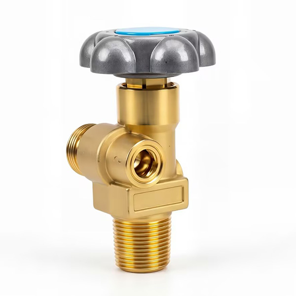
Different industrial, medical, and scientific gases require distinct sealing approaches to maintain safety and purity. Applying a standard industrial valve to a highly reactive or ultra-pure gas cylinder invites immediate operational failure. You must match the internal metallurgy and polymer selection to the specific chemical properties of the payload.
Oxygen service demands the strictest engineering controls due to the severe risks of adiabatic compression and adiabatic ignition. When a high-pressure valve is opened rapidly, the sudden rush of gas compresses the oxygen downstream against the regulator inlet. This rapid compression generates immense heat, often exceeding 1,000 degrees Fahrenheit in milliseconds.
If standard hydrocarbon-based lubricants or incompatible polymers are present inside the valve, this heat will cause them to spontaneously ignite. A dedicated high pressure oxygen cylinder valve must be manufactured from specific brass alloys, such as CW614N, which resist ignition under friction and heat. Assembly requires specialized oxygen-compatible lubricants, such as Krytox or Christo-Lube, which contain no combustible hydrocarbons.
Robust back-seating is mandatory for oxygen service. By isolating the packing ring during flow, the back-seat prevents high-velocity oxygen from eroding the PTFE. PTFE erosion generates particulate matter, creating an internal ignition hazard. Strict adherence to cleanroom assembly standards ensures no microscopic debris compromises the internal seals before the valve reaches the field.
Ultra-high purity (UHP) gases, calibration mixtures, and rare isotopes require a completely different approach to seal integrity. In these applications, even parts-per-billion (ppb) contamination from atmospheric air or outgassing valve components ruins the product. The valve must maintain a perfect vacuum before filling and hold absolute purity during discharge.
A standard packed valve fails UHP requirements. The dynamic PTFE packing ring traps microscopic pockets of atmospheric air during operation, which then diffuse into the gas stream. The threads on the wetted stem create dead space where previous gas mixtures linger, cross-contaminating expensive calibration gases.
To solve this, a specialty gas cylinder valve utilizes a tied-diaphragm architecture. Diaphragm valves eliminate the wetted stem seal entirely. A flexible metal membrane, usually Elgiloy or 316L stainless steel, separates the gas stream from the operating mechanism. When the handwheel is turned, it pushes down on the diaphragm, which in turn presses the seat against the orifice. This design achieves superior leak rates, often tested to 1x10^-9 mbar L/s of helium, and guarantees zero outgassing.
Material selection dictates the lifespan of specialty valves. Brass suits inert gases like argon or helium. Corrosive specialty gases, such as hydrogen chloride or ammonia, require stainless steel or Monel valve bodies to prevent chemical degradation of the internal sealing surfaces.
| Gas Category | Recommended Valve Material | Optimal Seal Architecture | Primary Failure Risk |
|---|---|---|---|
| Standard Industrial (Argon, Nitrogen) | Forged Brass (CW614N) | Soft-Seat (PCTFE/Nylon) with PTFE Packing | Seat deformation from overtightening |
| High-Pressure Oxygen | Ignition-Resistant Brass | Soft-Seat with Strict Back-Seating | Adiabatic ignition from hydrocarbon contamination |
| Ultra-High Purity (UHP) | 316L Stainless Steel or Brass | Packless Tied-Diaphragm | Atmospheric diffusion through dynamic seals |
| Corrosive / Toxic Mixtures | Stainless Steel, Monel, Hastelloy | Packless Diaphragm with Metal Seat | Chemical degradation of internal polymers |
Objective measurement of a valve's suitability requires evaluating multiple engineering dimensions. Procurement decisions must align the mechanical capabilities of the valve with the specific operational environment. You cannot rely on visual similarity; the engineering data stamped on the valve body dictates its safe usage.
The valve's maximum working pressure (MWP) must map perfectly to the cylinder's service pressure. Installing a valve rated for 200 bar on a 300 bar cylinder guarantees catastrophic seal failure and poses a lethal threat to operators. Engineers must verify the pressure ratings stamped on the valve body and ensure the inlet threads match the cylinder neck perfectly. A mismatch between a 25E taper thread and a 3/4" NPT cylinder neck will result in immediate blow-out under pressure.
Chemical compatibility dictates the lifespan of the internal seals. O-rings, packing materials, and valve body metals must be cross-referenced against the intended gas. Nitrous oxide causes certain elastomers to swell and extrude, leading to immediate seal failure. Carbon dioxide requires specific burst disc ratings to handle temperature-induced pressure spikes. Always consult compatibility charts provided by the manufacturer before specifying soft-seat materials.
Regulatory compliance serves as a baseline indicator of mechanical reliability. Specifying a tped certified gas cylinder valve provides immense operational security. TPED (Transportable Pressure Equipment Directive) certification guarantees the valve has passed rigorous European testing for pressure retention, impact resistance, and extreme temperature cycling. You can identify these valves by the Pi mark (π) stamped on the body.
This certification directly impacts facility operations. Using certified valves lowers insurance liability, streamlines cross-border transport of filled cylinders, and ensures seamless compliance during facility safety audits. Non-certified valves introduce unacceptable legal and operational risks, especially when transporting hazardous materials on public roadways.
The physical design of the handwheel impacts the longevity of the internal seals. Ergonomics dictate how much force an operator applies to close the valve. If a valve requires excessive closing torque to achieve a positive seal, operators will inevitably use wrenches or leverage tools to force it closed.
Excessive force crushes soft seats and permanently deforms metal-to-metal seals. Evaluating the required closing torque and selecting valves with ergonomically optimized handle wheels ensures operators can achieve a secure seal using only manual hand strength. A standard closing torque should not exceed 3 to 5 Nm for soft-seat valves. Handwheels manufactured from impact-resistant aluminum or high-density polymers protect the upper stem from drop damage, preserving the internal alignment.
Even perfectly engineered sealing mechanisms fail in real-world environments due to improper handling and inadequate maintenance. Cylinders endure harsh conditions: they are dropped, dragged across concrete, and exposed to weather. Identifying implementation risks is critical for maintaining facility safety and preventing gas loss.
Overtightening the handle wheel remains the leading cause of premature valve failure. When operators apply excessive torque, they crush the polymer seat inserts or score the brass mating surfaces. Once the internal geometry is deformed, the valve will continuously leak, regardless of how much force is applied subsequently. Stripped stems also result from this practice, rendering the valve completely inoperable and trapping the gas inside the cylinder.
Particulate contamination acts as the second major risk factor. Microscopic debris, such as rust, dust, Teflon tape shreds, or metal shavings, settles on the curved mating surfaces of the valve outlet. When a regulator is attached and tightened, this debris is driven into the metal-to-metal pressure seal. This compromises the connection, creating micro-leaks that drain cylinders over time and create hazardous atmospheres in enclosed spaces.
| Failure Symptom | Probable Cause | Corrective Action |
|---|---|---|
| Hissing sound from the handwheel when open | Worn or loose PTFE packing ring | Tighten packing nut slightly; replace packing if leak persists |
| Gas flow continues when valve is fully closed | Crushed soft seat or scored metal orifice | Remove cylinder from service; valve requires complete rebuild or replacement |
| Leak at the regulator connection point | Debris on the mating surface or damaged O-ring | Disconnect regulator, inspect and clean bullnose, replace regulator O-ring |
| Handwheel spins freely without engaging stem | Stripped upper stem threads from overtightening | Tag cylinder as defective; return to filler for safe venting and valve replacement |
Facilities must establish strict operational guidelines to protect valve seals. Operators must visually inspect all mating surfaces before attaching regulators. Any visible debris must be removed using approved, lint-free materials.
Follow this strict protocol for connecting regulators to high-pressure valves:
Secure the cylinder to a wall bracket or specialized cart to prevent tipping.
Remove the protective valve cap and inspect the external threads for impact damage.
Visually inspect the internal outlet orifice for dust, moisture, or metal shavings.
Wipe the regulator bullnose and the valve outlet with a dry, lint-free cloth.
Thread the regulator on by hand to ensure cross-threading does not occur.
Tighten the connection using the correct size wrench; never use adjustable wrenches that can slip and damage the brass fittings.
Stand to the side of the regulator, not in front of it, and open the handwheel slowly to engage the pressure.
External protection protocols are highly effective. Utilizing heat-shrink tamper-evident seals over the valve outlet post-filling ensures the internal components remain perfectly protected from environmental contaminants during transport and storage. These seals guarantee the end-user receives a clean, uncontaminated connection point.
Dangerous field practices must be aggressively addressed. Facility managers must explicitly warn against "cracking" open a high-pressure cylinder valve to blow out debris from the fitting seat. High-velocity gas can inject particles into the operator's skin, damage the internal packing rings, and, in oxygen service, cause adiabatic ignition. Mating surfaces must be cleaned manually, never with gas pressure.
Balancing procurement budgets against operational risk requires analyzing the overall value influencing factors of valve selection. Focusing solely on the initial purchase price inevitably leads to higher downstream costs. The hidden costs of cheap, uncertified valves rapidly outpace their initial savings.
Substandard machining tolerances lead to frequent replacements. Micro-leaks caused by poor packing ring compression result in continuous gas loss. In industrial settings, this gas loss directly impacts profit margins. Unexpected valve failures cause facility downtime, halting production lines while cylinders are safely vented and replaced. A stuck valve on a critical welding job costs exponentially more in lost labor than the price difference between a budget valve and a premium certified unit.
Procurement teams must know when to justify the premium for specialized architectures. Diaphragm-sealed specialty valves carry a higher upfront cost than standard O-ring or packed handle wheel designs. This premium is easily justified when calculating the return on investment based on the value of the gas contained.
For standard welding argon, a high-quality soft-seat valve is economically appropriate. For rare isotopes, toxic calibration mixtures, or ultra-high purity carrier gases for chromatography, the financial loss of a single leak dwarfs the cost of a premium diaphragm valve. The superior leak integrity of packless designs ensures expensive gases remain contained and uncontaminated, maximizing the yield of every cylinder purchased. You are paying for the guarantee that the gas mixture remains exactly as it was formulated at the fill plant.
Audit current cylinder valve failure rates to identify recurring overtightening issues or specific departments with high replacement metrics.
Consult directly with valve manufacturers to obtain specific leak-rate testing data and material compatibility charts for your required gases.
Update facility standard operating procedures to permanently eliminate seat-damaging practices like valve cracking.
Implement mandatory visual inspections of all mating surfaces using lint-free materials prior to any regulator attachment.
Mandate the use of external outlet protection, such as heat-shrink seals or threaded plugs, during all transport and storage phases.
A: The valve utilizes a back-seating mechanism. When the handwheel is turned to the maximum open position, a shoulder on the stem presses tightly against the upper bonnet. This metal-to-metal contact isolates the high-pressure gas from the threaded stem and packing ring, preventing leaks during active flow.
A: When closed, the internal piston is held under constant spring force against the valve body sealing surface. This mechanical pressure keeps the primary seat engaged. Simultaneously, a small internal O-ring seals the outlet off, preventing any residual gas in the cavity from escaping.
A: Oxygen service poses severe risks of adiabatic ignition during rapid pressure changes. Oxygen valves must be constructed from specific ignition-resistant brass alloys and assembled using specialized, hydrocarbon-free lubricants. Standard valves with incompatible polymers or oils will spontaneously ignite under high-pressure oxygen friction.
A: TPED stands for Transportable Pressure Equipment Directive. A TPED certified valve has passed rigorous European safety, pressure retention, and impact tests. This certification guarantees high manufacturing standards, ensuring the valve's sealing architecture can safely withstand extreme operational stresses.
A: A packed valve uses Teflon rings compressed around a rotating stem to prevent leaks, which can outgas or trap contaminants. A diaphragm valve uses a flexible metal membrane to completely isolate the gas stream from the operating mechanism, offering superior leak integrity and zero contamination for high-purity gases.
A: No. Cracking high-pressure valves to clear debris is highly dangerous. The high-velocity gas can cause severe injury, inject particles into the skin, and permanently damage the internal seals. Mating surfaces should always be inspected and cleaned manually with approved, lint-free materials.
A: Premature failure is primarily caused by operator overtightening, which crushes the internal seat. Other causes include the introduction of foreign particulate debris into the mating surfaces, using chemically incompatible gases that degrade soft polymer seals, and a general lack of routine inspection protocols.


