
Selecting the correct gas cylinder valve is a strict engineering decision. The valve serves as the primary barrier between high-pressure stored energy and the operational environment. Valve failure or misconnection is a severe safety and operational liability. Mis-specifying a valve for specific gas types introduces massive risks. These range from cross-contamination and compromised gas purity to catastrophic leaks, adiabatic compression ignition, and strict regulatory non-compliance. Operators must match the valve precisely to the chemical properties of the contained gas. You cannot use a standard brass valve for highly corrosive gases. You cannot use standard threads for flammable mixtures. This guide provides a systematic evaluation framework for selecting the correct valve mechanism, material, and connection standard. We evaluate gas properties, operational flow requirements, downstream equipment compatibility, and regional compliance mandates to ensure safe gas delivery systems.
Gas-to-Valve Matching is Non-Negotiable: Selection must be dictated by the chemical properties of the gas (inert, corrosive, toxic, flammable) to ensure material compatibility and prevent degradation.
Mechanism Dictates Control: The traditional handle wheel valve provides essential manual flow control, but specific high-purity or highly reactive applications require specialized diaphragm or tied-seat mechanisms.
Connection Standards Prevent Disasters: Adherence to standards like CGA V-1 ensures that incompatible gases cannot be physically connected to the wrong systems, minimizing hazardous misconnections across different gases.
Certification is a Baseline, Not a Feature: Specifying a TPED certified gas cylinder valve or CGA V-9 compliant valve is mandatory for legal operation and liability mitigation in respective regions.
Downstream Integration is Crucial: A valve does not operate in isolation; it must be perfectly matched with appropriate pressure regulators and gas filtration systems to ensure safe delivery.
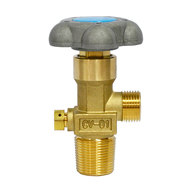
Operators require reliable, manual, and gradual control over high-pressure gas release. This control safely contains gases during transport and prevents dangerous pressure surges in downstream regulators during active use. The primary mechanism for achieving this remains the traditional Handle Wheel Valve. This design dominates the industry due to mechanical simplicity, robust construction, and intuitive operation.
Understanding the internal architecture of a standard valve helps you specify the right equipment. The core components work together to manage pressures that frequently exceed 200 bar (3,000 psi). Let us break down the specific internal parts:
Spindle: Translates the rotational motion of the handwheel into linear actuation.
Seat: The primary high-pressure seal, usually made of a soft polymer that presses against the brass or steel orifice.
Packing: Materials surrounding the valve stem to prevent gas from escaping into the atmosphere along the operational axis.
Safety Relief Device (SRD): Integrated directly into the valve body to vent excess pressure safely if the cylinder experiences extreme heat.
The handle wheel design remains the industry standard primarily due to ergonomic and safety benefits. Field operators wearing heavy personal protective equipment can easily grip and turn the wheel. The threaded spindle allows the valve to be opened very slowly. This slow opening capability mitigates the risk of adiabatic heat generation. When high-pressure gas rapidly releases into a lower-pressure regulator, the sudden compression of the gas in the regulator inlet generates temperatures high enough to ignite contaminants. This phenomenon causes many oxygen system fires. Gradual actuation provided by a handwheel prevents this rapid compression.
Standard handle wheel designs are the optimal choice for baseline applications. These include standard industrial gases, welding gas supplies, and basic laboratory gas distribution. In these environments, the primary requirements are durability, ease of use, and reliable shut-off capabilities.
Gas chemistry dictates valve construction. Selecting a valve without analyzing the specific properties of the gas leads to equipment failure, contamination, or severe safety incidents. Gases fall into three main groups, each requiring specific valve architectures.
Inert gases do not react with standard metals under normal conditions. For commonly used pure gases like nitrogen, argon, and helium, standard brass valves are the industry norm. Brass offers excellent machinability, sufficient tensile strength for high-pressure containment, and cost-effectiveness. The internal components typically utilize standard PTFE or nylon seats. These provide reliable sealing without the risk of chemical degradation.
Facilities managing various inert mixtures often consider utilizing a multi gas cylinder valve to consolidate inventory. A single valve design rated for multiple inert gases simplifies procurement and maintenance. However, operators must strictly manage cross-contamination risks. Dedicated purging protocols are mandatory when switching a multi-gas valve between different high-purity inert gases. This prevents trace contamination from affecting downstream processes.
Corrosive and toxic gases present severe challenges for valve materials. Standard brass bodies and conventional packing materials rapidly degrade when exposed to gases like ammonia, chlorine, or hydrogen chloride. Moisture in the air reacts with these gases to form highly aggressive acids, attacking the valve internals.
These applications necessitate tied-seat designs and corrosion-resistant materials. A tied-seat mechanism mechanically links the valve stem to the seat. If corrosion causes the seat to stick to the orifice, the mechanical linkage forces the seat open when the handwheel turns. This prevents the valve from jamming closed. Valve bodies for these gases must be machined from 316L Stainless Steel, Monel, or Hastelloy. Standard packed valves fail in these environments because the corrosive gas eventually permeates the packing, leading to dangerous atmospheric leaks of toxic material.
Flammable gases require specific safety mechanisms to prevent accidental ignition and manage over-pressurization. Safety relief device requirements vary significantly based on the gas. Flammable gases typically utilize burst discs combined with fusible plugs. The fusible plug melts at a specific temperature, exposing the burst disc. The disc then ruptures to vent the gas safely during a fire. This prevents the cylinder from exploding due to thermal expansion.
To prevent catastrophic misconnections, flammable gas valves utilize left-hand thread conventions globally. This physical engineering control ensures that an operator cannot accidentally connect a highly flammable hydrogen cylinder to a regulator and piping system designed for oxygen or other oxidizers. The left-hand threads are often denoted by a notch cut into the hex nut of the connection fitting.
Specialty gases differ significantly from industrial bulk gases. Industrial gases are typically rated by general purity percentages. Specialty gases, high-purity gases, and calibration mixtures are measured in parts per million or parts per billion of impurities. Maintaining this extreme purity from the cylinder to the analytical instrument requires specialized valve technology.
A standard packed valve introduces minute amounts of atmospheric contamination every time the stem actuates. Furthermore, the internal cavities of a standard valve create dead volume where older gas or atmospheric air becomes trapped. A specialty gas cylinder valve minimizes internal dead volume through streamlined internal porting. More importantly, these valves utilize diaphragm sealing mechanisms instead of traditional packing. A flexible metal diaphragm completely isolates the gas stream from the operating mechanism and the atmosphere. This eliminates leak paths, prevents atmospheric ingress, and stops outgassing from soft packing materials.
These specialized valves integrate directly with inline gas filtration systems. When supplying sensitive analytical instruments like gas chromatographs or mass spectrometers, even microscopic particulates generated by mechanical valve wear destroy the detector. Diaphragm valves generate virtually no particulates during operation, protecting downstream filtration and instrumentation.
Material traceability is a strict requirement for valves used in semiconductor manufacturing or pharmaceutical applications. Manufacturers must provide documented material heat numbers for every metal component in the valve. This proves the exact metallurgical composition of the raw materials. Furthermore, these valves undergo cleanroom assembly and specialized cleaning processes to ensure no hydrocarbon residues or manufacturing particulates remain inside the valve body prior to installation.
The cleanroom assembly process for high-purity valves typically involves several strict steps:
Ultrasonic cleaning of all machined metal components in a specialized solvent bath to remove cutting fluids.
Deionized water rinsing to strip away any remaining chemical residues from the ultrasonic bath.
Vacuum baking at elevated temperatures to drive off any trapped moisture within the metal pores.
Assembly within an ISO Class 4 or Class 5 cleanroom environment by technicians wearing full particulate-control garments.
Helium leak testing using a mass spectrometer to verify the integrity of the diaphragm seal and seat assembly.
Gas cylinder valves are heavily regulated pressure vessels. Operating non-compliant valves exposes facilities to severe legal liabilities, safety hazards, and regulatory fines. Certification is a mandatory baseline for operation.
Regulatory frameworks vary by global region. Within the European market, specifying a tped certified gas cylinder valve is a strict legal necessity. The Transportable Pressure Equipment Directive mandates rigorous design, testing, and manufacturing quality assurance standards for any pressure equipment transported across EU member states. Valves meeting these standards bear the Pi mark.
In North America, the Department of Transportation in the United States and Transport Canada enforce similar but distinct requirements. While the core safety principles align with European standards, the specific testing protocols, burst pressure ratios, and documentation requirements differ. Facilities operating globally must ensure their cylinder fleets comply with the specific directives of the region where the gas is transported and used.
Beyond regional transport directives, valves must adhere to specific design and performance standards. CGA V-9 and ISO 10297 dictate the rigorous cycle testing, leak rate maximums, and mechanical endurance required for a valve to be deemed safe for high-pressure service.
Physical connection standards are equally critical. CGA V-1, DIN 477, and BS 341 define the exact thread sizes, thread directions, and sealing face geometries for different gas types. These standards are engineered physical safeguards. By assigning unique connection profiles to specific gas families, these standards make hazardous misconnections physically impossible. An operator cannot thread an inert gas regulator onto an oxygen valve. Adhering to these standards is the primary defense against cross-contamination and reactive gas incidents.
To illustrate how connection standards prevent accidents, consider these common North American CGA assignments:
| CGA Connection | Gas Type | Thread Specification | Safety Feature |
|---|---|---|---|
| CGA 580 | Inert Gases (Argon, Nitrogen, Helium) | .965"-14 NGO Right-Hand Internal | Standard right-hand threads for non-reactive gases. |
| CGA 540 | Oxygen | .903"-14 NGO Right-Hand External | External threads prevent connection to inert internal threads. |
| CGA 350 | Flammable Mixtures (Hydrogen, Methane) | .825"-14 NGO Left-Hand External | Left-hand threads physically block connection to oxidizer lines. |
| CGA 660 | Corrosive Gases (Chlorine, Sulfur Dioxide) | 1.030"-14 NGO Right-Hand External | Requires a specialized PTFE washer for a highly secure seal. |
Selecting the optimal valve requires evaluating multiple technical dimensions and understanding the trade-offs between different materials and control mechanisms. The following parameters dictate long-term performance and safety.
The valve body material must withstand both the internal chemical attack from the gas and external environmental conditions.
| Material | Chemical Resistance | Durability & Wear | Primary Applications |
|---|---|---|---|
| Forged Brass | Excellent for inert gases. Poor for corrosives. | High mechanical strength, good thread life. | Nitrogen, Argon, Helium, standard Oxygen. |
| Chrome-Plated Brass | Slightly better external corrosion resistance than raw brass. | Maintains clean appearance, resists surface tarnishing. | Laboratory environments, medical gases, cleanrooms. |
| 316L Stainless Steel | Exceptional resistance to corrosive and toxic gases. | Very high durability, prone to thread galling if unlubricated. | Ammonia, Chlorine, UHP specialty gases, corrosive mixtures. |
| Monel 400 | Superior resistance to highly reactive halogens. | Extremely tough, highly resistant to stress corrosion cracking. | Fluorine, Hydrogen Fluoride, specialized chemical processing. |
The soft goods inside the valve are the most common points of failure. Seat and O-ring materials must be matched to the gas properties and operational temperature ranges.
PTFE (Teflon): The industry standard for most applications. Offers broad chemical compatibility and low friction, but can cold-flow under extreme pressure.
PCTFE (Kel-F): Superior to PTFE in high-pressure applications due to its higher mechanical strength and resistance to cold flow. Excellent for cryogenic and high-pressure oxygen service.
Viton (FKM): Excellent for high temperatures and many hydrocarbons, but degrades rapidly in the presence of ammonia or certain polar solvents.
Neoprene: Often used for specific refrigerant gases, offering good elasticity but limited chemical resistance compared to fluoropolymers.
Polyimide (Vespel): Used in extreme high-temperature environments where standard polymers would melt or deform.
The valve flow coefficient dictates the volume of gas that can pass through the orifice at a given pressure drop. The valve flow coefficient must align with the flow requirements of the primary pressure regulator and downstream flow control valves. Selecting a valve with an insufficient flow coefficient starves downstream equipment, causing regulator chatter and unstable delivery pressures. The outlet connection standard directly dictates the selection of the primary regulator. Mismatched connections require dangerous and highly discouraged adaptors.
Operators must weigh the operational simplicity of manual valves against the benefits of automation. Manual valves offer absolute reliability, require no external power, and provide direct tactile feedback to the operator. However, pneumatically actuated cylinder valves offer significant safety advantages in hazardous environments. Actuated valves tie directly into facility emergency shutdown systems. This allows toxic or flammable gas supplies to be isolated remotely in milliseconds during an alarm event. The trade-off involves higher upfront integration costs and the need for a reliable pneumatic control supply.
Even the most perfectly specified valve becomes a hazard if operated incorrectly or maintained poorly. Facilities must implement strict protocols to mitigate operational and lifecycle risks.
Rapidly opening a high-pressure valve causes a massive pressure spike in the downstream regulator. This ruptures the regulator diaphragm, damages internal gauges, or causes adiabatic ignition in oxygen systems. Operating a handle wheel gas cylinder valve requires disciplined technique.
Establish strict Standard Operating Procedures for operation. Follow this exact sequence to safely open a high-pressure cylinder valve:
Verify that the downstream flow control valve is completely closed.
Turn the pressure adjusting knob on the primary regulator counter-clockwise until it feels loose, ensuring no pressure will be forced through the regulator seat.
Stand to the side of the regulator, never directly in front of the pressure gauges.
Slowly open the cylinder valve hand wheel just enough to allow gas to enter the regulator.
Wait until the high-pressure gauge needle stops moving, indicating pressure equalization.
Open the cylinder valve completely to ensure maximum flow capacity.
Connecting regulators to valve outlets involves metal-on-metal friction. Stainless steel connections are particularly susceptible to galling, where friction causes the threads to cold-weld together, destroying both the valve and the regulator.
Specify correct torque values for all connections. Never use unapproved lubricants or PTFE tape on cylinder valve threads, especially on oxygen lines where hydrocarbons cause an explosion. Mandate regular visual thread inspections on both the valve outlet and the regulator fittings prior to every connection. Any deformed or flattened threads require immediate equipment quarantine.
Valves experience mechanical wear with every actuation. Seats degrade, spindles wear, and internal springs lose tension. Operating valves beyond their safe lifecycle leads to catastrophic leaks.
Define clear timelines for valve inspection, refurbishment, and retirement. Establish strict criteria for when to retire cylinders and valves entirely. This aligns with mandatory cylinder hydrostatic testing schedules. During hydrostatic testing, technicians remove the valve, inspect it, and either rebuild it with new soft goods or replace it entirely based on thread-wear tolerances and internal corrosion assessments.
Gas cylinder valve selection is a strict engineering exercise dictated by gas chemistry, pressure, downstream equipment, and regional safety legislation. The valve is the critical control point for hazardous stored energy, and its specification requires rigorous attention to detail.
To ensure safe and compliant operations, follow a strict shortlisting logic. Identify the exact gas properties, including flammability, toxicity, and required purity levels. Select compatible body and seat materials that resist chemical attack and mechanical wear. Determine the required physical connection standard to ensure perfect matching with downstream regulators and prevent hazardous misconnections. Verify that the selected valve carries the mandatory regional certifications.
Take immediate action to secure your gas delivery systems by following these next steps:
Audit your current cylinder fleet to verify regulatory compliance and material compatibility.
Inspect all valve threads and regulator connections for signs of galling, wear, or unauthorized lubrication.
Consult a certified gas systems engineer when designing systems for highly toxic, corrosive, or ultra-high-purity applications.
Request and review detailed technical specification sheets and material test reports from valve manufacturers before finalizing any procurement decisions.
A: The primary function is to safely contain high-pressure gas within the cylinder and provide reliable, manual, and gradual control over the gas release. The handle wheel design allows operators to open the valve slowly, preventing dangerous pressure surges and mitigating the risk of adiabatic heat generation in downstream regulators.
A: The required CGA connection is dictated by the specific gas type and is standardized by the Compressed Gas Association. You must consult the CGA V-1 standard or your gas supplier to find the assigned connection to ensure physical compatibility and prevent hazardous misconnections.
A: Specify a specialty valve when handling ultra-high-purity gases, calibration mixtures, or when supplying sensitive analytical instruments. Specialty valves use diaphragm seals instead of packing to eliminate atmospheric ingress, prevent outgassing, and minimize internal dead volume, ensuring the gas remains completely uncontaminated.
A: A TPED certified valve complies with the Transportable Pressure Equipment Directive, which is mandatory for pressure equipment used and transported within the European Union. It signifies that the valve has passed rigorous design, testing, and quality assurance standards and is legally approved for safe operation.
A: Opening an oxygen valve quickly causes rapid gas compression in the regulator, generating extreme adiabatic heat that can ignite contaminants and cause an explosion. Ensure the regulator is closed, stand to the side, and slowly turn the handwheel until the high-pressure gauge registers full cylinder pressure.
A: Valves should undergo a visual inspection before every use for thread damage or obvious leaks. Comprehensive internal inspection, refurbishment, or retirement must occur during the cylinder's mandatory hydrostatic testing cycle. Valves with severe thread wear, galling, or internal corrosion must be retired immediately.


