
Ever connected a gas regulator only to find mismatched threads? Picture this scenario. You are standing in a noisy fabrication shop. You might be in a critical care hospital unit. You wrestle with a high-pressure fitting. It simply refuses to seat properly. Improper gas connections pose severe safety risks. These range from rapid decompression and toxic leaks to explosive combustion. A proper mechanical gatekeeper prevents these hazards. This comprehensive guide breaks down how these standardized connections work. You will discover distinct variations across global standards. More importantly, you will acquire actionable safety tips for daily industrial operations.
Standardized Safety Protocols: A standardized connection ensures strict mechanical compatibility. It physically prevents dangerous cross-contamination between highly reactive or incompatible industrial gases.
Unique Threading Mechanisms: Distinct thread sizes and connection directions categorize specific gases. Non-flammable gases use right-hand threads. Flammable gases utilize left-hand threads for instant visual identification.
Global Standard Variations: North America universally uses the CGA system. Europe and the UK rely on DIN and BS standards. Understanding these regional differences prevents hazardous equipment mismatches during international operations.
Manual Flow Control Operations: The manual handwheel dictates the primary gas flow. Operators must follow strict operational and maintenance protocols. This prevents adiabatic pressure surges and mechanical equipment damage.
The Compressed Gas Association established rigorous guidelines. These regulate the safe handling and storage of compressed gases. Specifically, a CGA cylinder valve serves as the engineered connection point. It securely links a pressurized gas cylinder to a regulator or transfer line. Before these universal standards existed, mismatched connections frequently led to catastrophic workplace accidents. Facilities regularly dealt with explosive chemical reactions and severe high-pressure blowouts.
To systematically mitigate these risks, the industry adopted a highly specific dimensional design framework. Thread direction acts as a primary safety indicator here. Non-flammable gases typically utilize right-handed threads. Conversely, flammable gases require left-handed threads. You can visually identify these by a distinct V-shaped notch cut into the hex nut. For medical applications, the framework integrates the Pin-Index Safety System. This utilizes a yoke setup with specific pin placements that align uniquely with corresponding holes on the valve body. It ensures patients receive the correct life-saving medical gas without error.
Industry Trend Analysis: From a frontline engineering perspective, the compressed gas sector is experiencing a massive shift. We see a strong move toward advanced material engineering and digital traceability. Modern semiconductor fabrication and aerospace facilities demand ultra-high-purity valve designs. These components must guarantee absolute zero contamination. Furthermore, manufacturers are increasingly integrating RFID tags and digital pressure indicators directly into valve bodies. This transition toward smart cylinder management enhances real-time safety monitoring. It also streamlines inventory tracking across complex multinational supply chains. This evolution reflects a broader industrial push toward automated safety and zero-leakage sustainability.
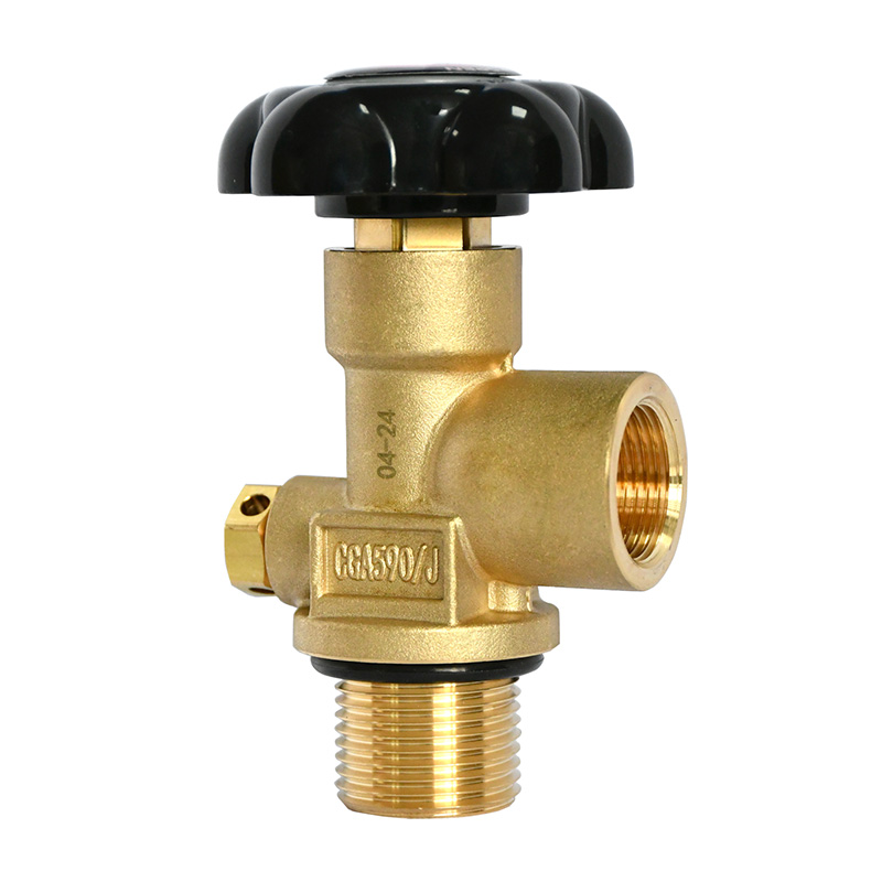
Understanding the physical components is essential for safe operation and routine maintenance. Each part serves a highly specific function. They contain and regulate gases that easily exceed internal pressures of 3,000 PSI.
The Valve Body: The primary structure is forged from heavy-duty materials. High-grade brass or stainless steel are the standard choices. Brass offers excellent durability and natural spark resistance for non-corrosive environments. Stainless steel is strictly reserved for highly corrosive gases or ultra-high-purity applications. Standard brass alloys would rapidly degrade under those harsh conditions.
The Manual Control Mechanism: This is the operator's direct line of defense. Turning the cylinder Handle Wheel Valve retracts the internal stem. This action allows pressurized gas to travel from the cylinder through the outlet. Proper and gradual operation is paramount. It prevents sudden pressure spikes that can obliterate downstream regulators or trigger spontaneous combustion in oxidizing environments.
The Outlet Connection and PRD: The outlet features precisely machined threads and a seating mechanism. This might be a bullet-nose nipple for metal-to-metal seals or a flat-face seal requiring a specific washer. Safety is further reinforced by the integrated Pressure Relief Device. Featuring a rupture disk or a fusible plug, this device safely vents gas into the atmosphere if the cylinder experiences severe over-pressurization or extreme environmental heat.
The framework categorizes hardware based on chemical properties and physical states. This intelligent design ensures regulators are physically incompatible with the wrong supply line. It essentially eliminates human error at the connection point. Let us look at the core specifications used in the field.
Oxygen Systems CGA 540: This standard universally applies to industrial and medical oxygen. An oxygen cylinder valve features a right-hand external thread paired with a bullet-nose nipple seal. Looking at premium industrial options like the GVC Series, these components are engineered for a nominal working pressure of 15 MPa and feature a 4mm nominal diameter. When handling these components, operators must strictly adhere to the zero-oil rule. Even microscopic traces of hydrocarbons can cause violent explosive combustion when exposed to highly concentrated oxygen.
Carbon Dioxide Systems CGA 320: Carbon dioxide requires a distinct connection. The CO2 cylinder valve utilizes a right-hand external thread but uses a flat-nipple design. High-performance models like the GVB Series handle 15 MPa working pressures and include integrated safety devices calibrated to trigger at 21 MPa. Unlike oxygen setups, this connection mandates a non-metallic washer. Operating without this nylon or Teflon washer results in immediate freezing gas leaks. This can cause severe frostbite and rapid cylinder depletion.
Inert Gases CGA 580: For non-reactive gases like Argon and Nitrogen, the standard is CGA 580. It features right-hand internal threads and a bull-nose seating mechanism. This internal threading prevents operators from accidentally attaching external-threaded regulators meant for oxidizing gases. It maintains absolute system integrity during delicate laboratory applications.
Flammable Gases CGA 510 and CGA 300: Flammable gases demand the most stringent safety indicators. These standards employ left-hand threading. The hex nut features a highly visible machined notch. This serves as a universal visual and tactile warning that the contents require specialized handling.
The global landscape of industrial gas transport is highly fragmented. North America relies exclusively on the CGA framework. However, multinational operations frequently encounter global variations. Imported heavy machinery and international maritime shipping operations often utilize different manufacturing standards.
| Standard System | Primary Region | Thread Characteristics | Compatibility Risk |
|---|---|---|---|
| CGA | North America | Unified National threads with specific left or right orientation | Baseline standard, mechanically incompatible with EU or UK gear |
| DIN 477 | Germany and broader EU | Distinct thread pitches, diameters, and seating angles | High risk of cross-threading if forced into North American equipment |
| BS 341 | United Kingdom | Whitworth thread profiles | Requires native BS regulators, zero direct crossover allowed |
Safety engineering protocols strongly advise against using aftermarket adapters to bridge these systems. Utilizing uncertified adapters introduces multiple points of failure. It significantly increases the risk of high-pressure leaks and mechanical blowouts. Facilities must source natively compatible regulators for their specific hardware to maintain compliance.
Selecting the appropriate hardware requires a methodical approach. Improper selection compromises system safety and severely hampers operational efficiency. Here is how engineers evaluate their requirements on the floor.
Verify Gas Type and Pressure: Identify the specific gas first. This dictates the required standard number. Attempting to bypass this rule creates severe hazards. Next, verify the working pressure. Standard inert gases use basic connections. However, high-pressure variants exceeding 3,000 PSI require specialized connections to handle the intense mechanical stress safely.
Match the Material to the Application: The structural material must align flawlessly with the chemical corrosiveness of the gas. Standard brass is highly effective and economical for inert gases. Take the GVA Series for example. It utilizes premium brass for reliable 15 MPa operation. Conversely, when handling corrosive agents like anhydrous ammonia, stainless steel is absolutely mandatory. Stainless steel prevents internal chemical degradation and ensures absolute gas purity over an extended operational lifespan.
The primary interface between an operator and a high-pressure system is the manual control mechanism. Proper operation is a critical safety requirement mandated by occupational safety organizations. Mishandling easily leads to catastrophic equipment failure.
Proper Opening Technique: Always stand to the side to remove yourself from the direct line of fire. Do not stand in front of or behind the pressure regulator. Before attaching the regulator for certain non-flammable gases, briefly crack the valve to blow out accumulated dust. Once attached, open the handwheel extremely slowly. Rapid opening causes adiabatic compression. This sudden spike in pressure generates intense heat which can ignite internal contaminants. Once fully pressurized, open the valve completely to engage the back-seat seal. This prevents high-pressure gas from leaking around the internal stem.
Leak Testing Protocols: Routine leak testing is a non-negotiable workplace practice. Visual inspections cannot detect micro-leaks. Apply an approved oil-free leak detection fluid generously around the neck threads and outlet. Wait for at least 60 seconds. Active bubbles indicate a pressurized leak. Never use standard dish detergents. They often contain petroleum derivatives that create an immediate fire hazard when mixed with oxidizing gases.
Even with rigorous safety protocols, operators occasionally encounter mechanical issues on the floor. Understanding these nuances allows for efficient troubleshooting without compromising industrial compliance.
Hissing After Connection: A persistent hissing sound indicates a seating failure. In carbon dioxide applications, the common culprit is a missing or deformed nylon washer. The flat nipple design requires this non-metallic washer to create a gas-tight seal. Forgetting it causes profuse leaking regardless of applied torque. Depressurize the system entirely and inspect the threads with a flashlight before retrying.
Regulator Refuses to Thread: Stop immediately if you struggle to thread a regulator. The system intentionally uses incompatible profiles to prevent cross-contamination. Check for left-hand versus right-hand mismatches. Never use pipe wrenches or excessive force. Doing so permanently destroys the soft brass threads and creates an extreme blowout hazard.
Stuck Handwheel: Thermal expansion or internal corrosion typically causes a stuck wheel. Sometimes an operator previously over-tightened it in the closed position. Under no circumstances should you use a leverage bar to force it open. Mechanical leverage will easily shear the internal brass stem completely off. This causes high-pressure gas to vent uncontrollably. Tag the cylinder as defective and contact your supplier for a safe replacement.
Navigating high-pressure gas systems requires a solid understanding of standardized connections. Recognizing specific thread profiles and operational protocols prevents dangerous leaks and catastrophic equipment damage. Always match the correct hardware to your specific gas type. Routine inspections keep your facility safe and compliant. For industrial operations demanding absolute reliability, upgrading to engineered solutions is a necessity. Explore the comprehensive range of premium cylinder control components at ZXHP Gas to secure your workplace operations today.
While some approved adapters exist for highly specific laboratory applications, safety organizations highly discourage their general use. Adapting different gas types introduces a severe risk of catastrophic cross-contamination, unexpected chemical reactions, and explosions. You should always use a regulator that natively matches the standard of the cylinder.
This specific standard requires a flat washer to seal properly. It does not use a metal-to-metal bullet-nose connection. If this non-metallic washer is missing, worn out, severely compressed, or cracked from previous overtightening, the connection will invariably leak. You should always inspect and replace this washer regularly to ensure a gas-tight seal.
A distinct V-shaped notch machined into the outside of the hex nut indicates that the fitting utilizes a left-hand thread. In the North American system, left-hand threads are universally used to signify that the cylinder contains a highly flammable gas. This physical indicator prevents operators from accidentally connecting flammable gas equipment to oxidizing or inert gas cylinders.
Connections should be tightened firmly using the appropriate correctly sized cylinder wrench. Excessive overtightening permanently damages the soft brass threads or crushes the internal seating nipple. This leads to chronic leaks. Furthermore, you must never use Teflon tape or pipe dope on these connections unless explicitly specified by the manufacturer.
Minor external parts like a cracked plastic or metal handwheel can sometimes be replaced by the end-user if explicitly permitted by the supplier guidelines. However, internal repairs, stem replacements, or complete body swaps should only be performed by certified gas professionals at a dedicated filling facility. Attempting internal repairs on a pressurized cylinder poses a lethal risk of explosive decompression.
Operators should perform a visual inspection before every single use. Look for thread damage, debris, or signs of impact. In commercial settings, formal documented inspections and leak tests should occur during every cylinder changeout and as part of a routine monthly facility safety audit.
A residual pressure valve incorporates a specialized internal mechanism designed to retain a small amount of positive pressure inside the cylinder even when the main handwheel is fully open and the gas is depleted. This retained pressure prevents ambient air and moisture from entering the cylinder, thereby eliminating internal corrosion and maintaining gas purity for the next fill cycle.


