
Industrial and medical gas environments operate under immense physical stress. A single high-pressure valve failure can trigger catastrophic blowouts. Such failures endanger plant personnel and halt critical operations. Navigating mandatory regulatory frameworks guarantees baseline industrial safety. However, dense technical jargon often overwhelms procurement teams and system engineers.
The Transportable Pressure Equipment Directive, officially Directive 2010/35/EU, serves as the definitive legal framework governing gas cylinders and associated accessories within the European Union. While European in origin, its rigorous standards serve as a global benchmark for pressure containment. In this comprehensive guide, you will learn exactly what a TPED gas cylinder valve requires. We will cover critical design parameters, exhaustive testing protocols, and essential buying criteria to keep your equipment supply chain secure.
Key Takeaways
A compliant valve must permanently bear the Pi mark. This signifies irrefutable adherence to European transportable pressure directives.
Stringent material selection, burst testing, and micro-leak resistance are mandatory. These factors prevent catastrophic blowouts under extreme pressure.
Different operational environments demand specific designs. Examples include ignition-resistant oxygen valves or contamination-preventing residual pressure variants.
Proper documentation is strictly non-negotiable for certification. This includes a batch-specific EU Declaration of Conformity and traceability markings.
Understanding regional thread standards is crucial when specifying equipment for a particular industrial setup.
The Transportable Pressure Equipment Directive establishes a stringent regulatory framework. Its primary goal is guaranteeing the highest level of safety for transportable pressure equipment. A secondary objective involves facilitating the seamless movement of these critical goods across European member states. Compliance with this directive is a strict legal requirement for any equipment utilized in high-pressure gas transport.
The most visible indicator of this compliance is the Pi mark. Much like the CE mark functions for general consumer electronics, the Pi mark is exclusively dedicated to transportable pressure equipment. When a valve displays this distinct symbol, it serves as undeniable proof. The component has survived rigorous third-party assessment and meets all essential safety parameters dictated by the directive.
A frequent misconception persists in the field. Many assume the directive applies solely to the heavy metal cylinder itself. In reality, the regulation encompasses the entire pressure receptacle system. The gas cylinder valve is arguably the most critical component within this scope. It acts as the primary control mechanism holding back immense stored energy. If the valve fails, the structural integrity of the entire cylinder assembly is instantly compromised.
Furthermore, while the directive originates in Europe, its technical foundations are deeply rooted in international ISO standards. Consequently, this compliance is recognized worldwide. Industrial facilities in Asia, the Middle East, and the Americas routinely specify these certified valves. Doing so mitigates operational risk and ensures unyielding reliability.
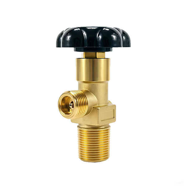
Material compatibility dictates valve survival. Engineers must select raw materials carefully during the design phase. This prevents chemical reactions, internal corrosion, or structural degradation over time. Standard inert gases like argon or nitrogen flow safely through high-grade brass, specifically CW614N, due to its excellent machinability and durability. In contrast, corrosive gases such as ammonia demand 316L stainless steel to resist severe chemical attacks. Reactive gases might require specialized alloys to prevent hydrogen embrittlement.
Pressure ratings present another formidable engineering challenge. A compliant valve must manage immense internal forces. Standard industrial valves are typically rated for working pressures of 200 bar or 300 bar. However, the design must account for a massive safety factor. Valve bodies are forged to withstand test pressures that often exceed 1.2 to 1.5 times the maximum working pressure. A 200-bar valve, for example, is routinely hydrostatically tested at 240 bar. This ensures that sudden pressure spikes during a rapid filling process do not lead to mechanical shearing.
Specifically, industrial and medical gas cylinders endure brutal environmental conditions. Operators handle cylinders in freezing outdoor facilities in winter. Minutes later, the same cylinder might sit near a high-heat industrial furnace. The regulations mandate that valves function flawlessly across extreme temperature ranges. Typical testing covers negative 20 degrees Celsius to positive 65 degrees Celsius. The internal components, particularly non-metallic seals and specialized lubricants, must resist cracking at low temperatures and extrusion under high heat.
Safety is intrinsically linked to everyday operability. Plant operators must be able to open and close the valve smoothly. They should not need to apply excessive torque, even when the cylinder is fully pressurized. The internal spindle and seat design must prevent binding or galling. This guarantees precise flow control during every single use.
Before a newly designed valve reaches mass production, it undergoes a punishing Type Approval process. An independent organization accredited by a national authority, known as a Notified Body, meticulously assesses the technical drawings. They review material specifications and test physical prototypes. The design must strictly conform to harmonized standards. EN ISO 10297 outlines the specific performance requirements for these cylinder valves.
Physical validation forms the core of this certification. When a technician mounts a cylinder on a filling rack, they rely entirely on the structural soundness of the forging. Valves are subjected to extreme hydraulic over-pressurization until the point of failure. This burst testing proves the forging can handle pressures significantly exceeding regulatory minimums.
Additionally, valves must demonstrate near-zero leakage. Advanced helium mass spectrometry detects microscopic leaks. This ensures both internal seat leakage and external atmospheric leak rates remain below strict safety thresholds.
To simulate real-world abuse, valves undergo severe impact testing. A heavy weight is dropped directly onto the valve assembly. The mechanism must not shear off or release catastrophic pressure. Furthermore, the internal mechanism is mechanically cycled for thousands of iterations at full working pressure. Subsequent leak tests verify that the internal seat and spindle have not degraded from friction. Self-certification is strictly prohibited. An accredited Notified Body must physically oversee the testing protocols and verify the raw data.
The regulatory framework applies to a wide variety of valve designs. Each is engineered for specific industrial, specialty, or medical applications. Understanding the mechanical distinctions between these mechanisms is vital for specifying the correct equipment for your facility.
Below is a core technical comparison of common valve configurations:
| Valve Type | Primary Application | Core Engineering Feature | Typical Working Pressure |
|---|---|---|---|
| Handle Wheel Valve | General Industrial Gases | Heavy-duty brass forging, manual spindle actuation, high flow rate. | 200 bar / 300 bar |
| Oxygen Valve | Medical & Industrial Oxygen | Hydrocarbon-free cleaning, adiabatic ignition resistance, BAM-approved seals. | 200 bar / 300 bar |
| Residual Pressure Valve | High-Purity and Specialty Gases | Integrated cartridge maintaining 3 to 5 bar positive internal pressure to block contamination. | 200 bar / 300 bar |
The standard high-pressure Handle Wheel Valve is the most ubiquitous design found in the heavy industrial gas sector. It relies on a manually operated handwheel connected to a threaded spindle to open and close the gas flow. As the operator turns the handwheel, the spindle lifts the sealing material off the valve seat. This allows high-pressure gas to exit the cylinder.
These units feature incredibly robust designs. Built with heavy-duty forgings, they withstand harsh environments, rough handling by forklift operators, and constant connection to heavy regulators. The internal spindle and seat materials resist wear and tear during frequent high-pressure operation. This minimizes the risk of internal leaks over a decade-long lifespan.
An oxygen cylinder valve requires highly specialized engineering. High-pressure oxygen presents unique, volatile hazards. Oxygen vigorously accelerates combustion. When a valve is opened rapidly, the sudden rush of high-pressure oxygen into a dead-end passage causes extreme localized heating. This phenomenon is known as adiabatic compression. If incompatible materials or microscopic debris are present, this heat can trigger a catastrophic internal fire.
To mitigate this severe risk, standards mandate strict material compliance. All components, especially non-metallic seals and lubricants, must be strictly oxygen-compatible. The valve undergoes specialized adiabatic impact testing to prove it will not ignite under rapid pressurization. Additionally, the manufacturing process incorporates rigorous cleaning protocols. The final product must be entirely free of hydrocarbon contaminants before it is sealed for shipping.
A residual pressure cylinder valve is an advanced design increasingly mandated for high-purity, medical, and specialty gas applications. This intelligent mechanism incorporates a specialized internal cartridge. The cartridge automatically closes when the internal cylinder pressure drops to a specific low threshold, typically between 3 to 5 bar.
Even if an end-user carelessly leaves the main handwheel in the open position after emptying the tank, the valve physically blocks the remaining gas from escaping. By maintaining this positive pressure, the mechanism prevents atmospheric air, ambient moisture, and external pollutants from back-flowing into the cylinder. This protects the interior walls from rust and drastically reduces the cost and time required to purge and clean the cylinder before its next fill.
A compliant valve is essentially a highly documented asset. The directive requires mandatory physical stampings on the valve body. This ensures lifetime traceability from the foundry to the end-user. Permanent markings typically include the official Pi mark, a four-digit Notified Body identification code, and the manufacturer registered trademark. The date of manufacture and the specific inlet thread specification are also clearly stamped.
Physical markings on the metal must be backed by official paperwork. The manufacturer is legally obligated to draft and provide an EU Declaration of Conformity for every production batch. This vital document legally binds the manufacturer to the claim that the specific batch meets all directive requirements and relevant ISO testing standards.
Quality control extends long after the component leaves the factory floor. Manufacturers maintain detailed, digitized records of material batches using EN 10204 3.1 material certificates. Assembly dates and testing telemetry are kept on file for a minimum of ten years. This rigorous batch tracking ensures absolute accountability. It facilitates rapid, highly targeted recalls in the highly unlikely event of a field failure.
When integrating these components into an industrial gas network, understanding highly specific thread standards is an absolute necessity. The interface between the cylinder, the valve, and the downstream regulator is the most vulnerable point in any high-pressure system. Standardized outlet connections are dictated by regional regulations based on the gas type. This physically prevents operators from accidentally connecting an incompatible gas, like flammable hydrogen, to a system designed for oxidizing oxygen. Common global standards include DIN 477 in Europe, AIGA in the Asia-Pacific region, and CGA in North America.
Equally important are the inlet threads. This is the critical mechanical connection between the valve and the high-pressure cylinder neck. The thread profile must match the cylinder precisely to prevent catastrophic ejection under pressure. The industry primarily utilizes taper threads, such as 25E or 17E, which wedge tightly together as they are torqued. Alternatively, parallel metric threads rely entirely on an engineered O-ring for sealing.
Connecting the assembly requires strict adherence to engineering torque specifications. Installation must be performed using calibrated torque wrenches. Under-torquing leads to insidious high-pressure micro-leaks. Over-torquing can permanently deform the brass threads or crack the cylinder neck, completely compromising vessel safety.
As industrial automation and green energy initiatives accelerate, the requirements for gas cylinder valves are undergoing a significant transformation. Recent market data highlights a strong movement toward digital traceability and higher pressure thresholds. The traditional stamped brass valve is rapidly evolving into a smart component. Many modern compliant valves now integrate embedded RFID chips or durable two-dimensional matrix barcodes directly into the forging. This allows filling plants to instantly scan and retrieve the entire manufacturing history, maintenance logs, and exact cycle counts of the valve. Such digitization vastly improves safety audits and lifecycle management.
Furthermore, the global push toward hydrogen energy is fundamentally altering pressure requirements. Standard industrial gases traditionally operate at 200 bar. However, the storage and transport of hydrogen in advanced composite cylinders demand valves capable of safely managing 300 to even 700 bar. This requires a paradigm shift in metallurgical engineering. Valve producers are developing advanced, hydrogen-embrittlement-resistant alloys and ultra-resilient polymer sealing technologies that far exceed legacy testing baselines.
Finally, the semiconductor and electronics manufacturing sectors are driving demand for ultra-high-purity gas containment. In these environments, even parts-per-billion contamination can ruin millions of dollars of microchips. Consequently, the industry is seeing a massive surge in the adoption of advanced residual pressure valves combined with specialized, particle-free cleanroom assembly processes. This ensures the valve acts as an absolute barrier against microscopic atmospheric intrusion.
Selecting the correct equipment requires a systematic, evidence-based evaluation of your operational parameters. This ensures both plant safety and filling efficiency.
Identify the Gas Type and Material Compatibility
The specific gas dictates the metallurgical composition. Standard inert gases are perfectly suited for traditional brass valves. Corrosive gases require stainless steel. Medical oxygen necessitates a specialized valve that has undergone strict hydrocarbon-free cleaning and utilizes non-metallic seals approved for oxygen service.
Determine the Working Pressure
Match the pressure rating of the valve exactly to your cylinder specifications. A valve rated for 200 bar must never be installed on a 300-bar composite cylinder system. Ensure the design pressure explicitly aligns with your facility filling and distribution infrastructure to prevent blowout risks.
Select the Optimal Valve Mechanism
Evaluate your daily operational workflow. A standard handwheel design is sufficient for basic industrial welding. In contrast, if maintaining gas purity and preventing internal cylinder moisture is a priority, investing in a residual pressure mechanism is critical. This yields long-term cost savings by eliminating the need for exhaustive pre-fill cylinder purging.
Verify Certifications and Documentation
Never assume compliance based solely on visual appearance. Always request the EU Declaration of Conformity from the supplier. Cross-reference the four-digit Notified Body number stamped on the metal body with official European Commission databases. This confirms the certification is authentic and currently valid.
The issuance of a certification does not guarantee infinite operational life. High-pressure gas equipment is subjected to extreme mechanical stress. According to international transport regulations, gas cylinders and their attached valves must undergo periodic reassessment. Before every single refill, technicians must perform a visual inspection for thread damage, bent spindles, and severe corrosion. This is followed by a stringent post-fill leak test.
When a unit fails a routine inspection or becomes difficult to operate, facility managers must decide between refurbishment and replacement. While some rebuild kits contain replacement O-rings and seats, industry best practices increasingly favor total replacement. Given the critical safety function of the component, replacing an aging unit ensures factory-tested reliability. It mitigates the severe liability associated with improper field repairs.
Ultimately, these components have a finite operational lifespan. This is typically aligned with the ten-year hydrostatic test interval of the cylinder itself. Once a valve has reached the end of its safe life, or if it has been subjected to extreme physical trauma like a forklift drop, it must be safely decommissioned. Standard industry practice involves permanently destroying the inlet threads or drilling through the body. This ensures the compromised unit can never re-enter the high-pressure supply chain.
Specifying the correct gas cylinder valve is a fundamental commitment to operational safety and product reliability. It goes far beyond mere regulatory compliance. Navigating the stringent requirements of the Transportable Pressure Equipment Directive ensures that your facility is protected against catastrophic high-pressure failures.
Plant engineers and procurement teams must thoroughly understand the significance of the Pi mark, the rigor of the testing protocols, and the nuances of material compatibility. This knowledge empowers you to make highly informed purchasing decisions. Whether you are sourcing a standard industrial handwheel design or an advanced residual pressure mechanism for high-purity applications, precision is key.
Do not compromise on safety. Always consult with certified manufacturers to review your specific gas control needs. If you are looking to upgrade your high-pressure gas infrastructure with fully compliant, traceable, and secure components, explore the extensive range of certified valves at zxhpgas.com to find the exact match for your operational requirements.
The Pi mark is the official regulatory stamp indicating that the equipment complies entirely with the European Union Transportable Pressure Equipment Directive. It signifies that the valve design, raw materials, and manufacturing processes have undergone rigorous third-party testing by an accredited Notified Body. This certification ensures the component can safely withstand extreme high pressures, severe temperature variations, and physical impacts without failing.
While both deal with pressure equipment, PED applies to stationary pressure equipment like factory boilers and fixed piping systems. In contrast, TPED applies specifically to transportable pressure equipment, such as gas cylinders, their valves, and tube trailers that are moved across public roads. A valve designed for a mobile gas cylinder must carry the Pi mark, not just the standard CE mark associated with PED.
No, you absolutely cannot use a standard industrial valve for oxygen. An oxygen-specific valve must be meticulously engineered and processed to prevent ignition. High-pressure oxygen can cause spontaneous, explosive combustion if it encounters even microscopic amounts of hydrocarbons, oils, or incompatible polymers during rapid pressurization. Therefore, these valves undergo specialized cleanroom processing and utilize strictly tested, ignition-resistant internal seals.
A residual pressure valve is designed to maintain a small, continuous positive pressure inside the gas cylinder, even when the user accidentally leaves the handwheel in the fully open position. This intelligent mechanism is crucial because it physically blocks atmospheric air, moisture, and airborne pollutants from flowing backward into an empty cylinder. By preventing internal contamination, it protects the cylinder walls from rust and significantly reduces the maintenance costs associated with purging.
The manufacturing date is permanently stamped into the metal body of the valve, usually near the neck or hex base. It is typically formatted as the year and month. This date is critical for maintenance tracking, as it determines when the valve must undergo mandatory periodic inspection or be decommissioned according to local transport regulations.
Valves are typically subjected to rigorous mandatory inspection and testing at the same intervals as the gas cylinders to which they are attached. Depending on the specific gas type and local transport regulations, this major interval is usually every five to ten years. However, a basic visual inspection and a highly sensitive leak check must be performed by certified filling plant technicians before and after every single gas refill to ensure ongoing operational integrity.
Yes. While fundamentally a European Union directive, the rigorous engineering and testing standards it enforces are recognized and highly respected globally. Many international markets, advanced industrial facilities, and multinational gas corporations outside of Europe explicitly specify these certified valves in their procurement requirements. The Pi mark serves as a universally understood benchmark for uncompromising safety.


