
In high-pressure gas systems, the cylinder valve serves as the primary mechanical barrier between contained potential energy and the operational environment. Specifying an inadequate valve immediately compromises system integrity. This mistake leads to hazardous leaks, gas contamination, or catastrophic pressure releases on the facility floor. Facility managers and engineers must balance operational accessibility with strict safety tolerances to maintain secure gas distribution. You need to evaluate internal mechanics, safety features, and compliance standards to specify the correct hardware. This applies directly to industrial, medical, or specialty gas applications. We will break down the core functions, safety integrations, and strict material requirements necessary to manage high-pressure environments safely. Using the right Handle Wheel Valve prevents downtime and protects personnel.
Primary Function: The handle wheel valve dictates the initial flow of gas from the cylinder to the downstream regulator, relying on precise stem and seat mechanics to prevent high-pressure leakage.
Safety Integration: Modern valves incorporate secondary safety mechanisms, such as Pressure Relief Devices (PRDs) and back-seating features, to mitigate extreme temperature risks and stem leaks.
Application Specificity: Gas type dictates valve construction; a high pressure oxygen cylinder valve requires strict material compatibility to prevent adiabatic ignition, whereas a multi gas cylinder valve demands versatile, corrosion-resistant metallurgy.
Standardization: Adherence to standards like the CGA V-9 cylinder valve specification is non-negotiable for ensuring interoperability, safety, and regulatory compliance.
The mechanical translation of turning the handwheel directly controls the release of contained gas. When you rotate the wheel counter-clockwise, the threaded valve stem lifts upward. This movement pulls the valve seat away from the internal orifice. It breaks the seal and allows gas to travel from the cylinder into the valve body and out through the discharge port. Maintaining a gas-tight closure under high pressure requires precise engineering. System pressures frequently exceed 2,000 to 3,000 psi. The valve seat utilizes highly durable elastomeric materials like PCTFE or Nylon. Some applications require specialized metallic seals depending on the gas properties. These materials resist deformation while providing a flawless seal against the machined metal orifice.
The stem threads require specialized lubricants that will not react with the gas payload. Inert gas valves might use standard industrial lubricants, while oxygen valves strictly require fluorinated, non-hydrocarbon greases to prevent ignition. The orifice size within the valve body also dictates the maximum flow coefficient, which engineers must match to the downstream regulator's capacity.
Understanding the operational boundary of a handle wheel gas cylinder valve is fundamental to system safety. The valve acts strictly as a manual isolation point. We use it for coarse on/off control. You must never use it for precise flow adjustment or throttling. Attempting to throttle gas flow by partially opening the valve causes high-velocity gas to rush past the seat. This creates wire drawing. The friction rapidly erodes the seat material and destroys the valve's ability to seal completely. You must install downstream gas pressure regulators to manage flow rates. Regulators reduce the high cylinder pressure and maintain a steady outlet pressure to the system. They compensate automatically as internal cylinder pressure drops during usage.
The back-seating mechanism provides a critical safety redundancy in high-pressure applications. Traditional valve stems rely on packing materials to prevent gas from escaping up through the threads. Packing wears down over time due to friction and environmental degradation. The back-seat acts as a secondary mechanical seal engineered directly into the upper portion of the valve body.
When you fully open the handle wheel, turning it until it stops, the upper collar of the valve stem engages tightly against a machined surface inside the bonnet. This metal-to-metal contact isolates the stem packing from the high-pressure gas flow entirely. Engaging this secondary seal is an operational best practice. It actively prevents high-pressure gas from escaping through the threaded stem during active use. This feature proves vital for mitigating leak risks in high-pressure oxygen systems and flammable gas deployments. Even minor fugitive emissions in these environments create severe fire or explosion hazards.
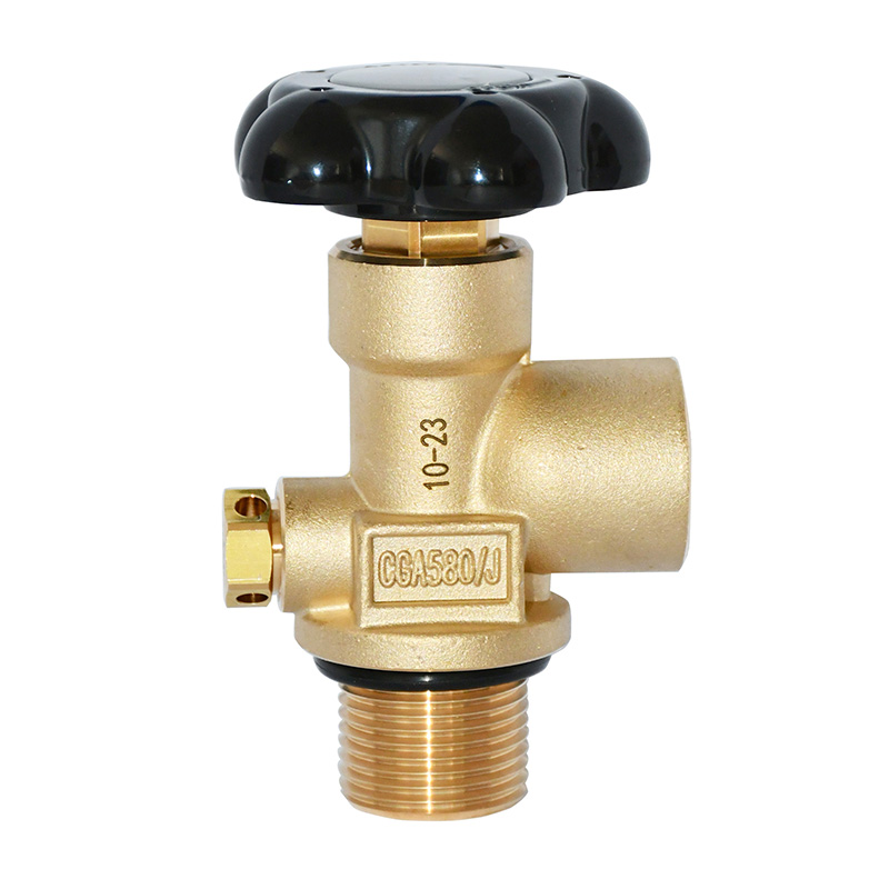
Pressure Relief Devices (PRDs) are engineered fail-safes integrated directly into the valve body. They protect the structural integrity of the cylinder. These devices activate under specific extreme conditions to prevent catastrophic cylinder explosions. We typically see three primary types of PRDs in the field.
Rupture Disks: These consist of a thin metal membrane designed to burst at a predetermined pressure threshold. They instantly vent the cylinder contents if internal pressure exceeds safe limits due to overfilling. Engineers calculate the burst pressure based on the cylinder's test pressure, usually setting it at 5/3 of the normal working pressure.
Fusible Plugs: These utilize a specialized metal alloy engineered to melt at a specific temperature, typically around 165°F or 212°F. When exposed to external fire, the plug melts and safely releases the gas before the cylinder metal weakens.
Combination Devices: These integrate both a rupture disk and a fusible plug in series. This configuration requires both excessive heat and excessive pressure to activate. It prevents accidental venting during temporary pressure spikes.
Regardless of the specific type, PRDs serve a critical role in facility safety. They safely vent gas during external fire events or extreme ambient temperature exposure. This prevents the cylinder from rupturing and protects personnel from high-velocity shrapnel.
Standard handle wheel valves allow the cylinder to completely depressurize if left open. When the internal pressure drops to zero, the cylinder becomes vulnerable to atmospheric backflow. Ambient air, moisture, and airborne particulates enter the empty cylinder. This leads to internal corrosion and severe contamination of future gas fills. Residual Pressure Valves (RPVs) solve this problem. They incorporate a specialized internal cartridge that retains a positive pressure baseline within the cylinder. This baseline stays between 30 and 50 psi even when you leave the handle wheel in the fully open position.
Evaluating the trade-off between standard configurations and RPVs requires analyzing operational priorities. RPVs physically block atmospheric backflow. They ensure the interior of the cylinder remains pristine. This capability drastically reduces cylinder maintenance costs. You eliminate the need for internal washing, baking, and vacuum purging before refilling. It also preserves the purity of highly sensitive specialty gases. RPV-equipped valves carry a higher initial procurement cost and require specific filling adapters at the gas plant. The long-term operational advantages in gas purity and cylinder preservation make them highly advantageous for advanced manufacturing and laboratory applications.
Oxygen-enriched environments present severe operational risks that demand highly specialized valve engineering. The primary hazard is adiabatic compression. If you open a standard valve too rapidly, the sudden rush of high-pressure oxygen into the downstream regulator compresses the gas in the dead space. This rapid compression generates intense localized heat. Temperatures often exceed 1,000°F in milliseconds. If any hydrocarbon contaminants, metallic particles, or incompatible polymers exist in the valve or regulator, this heat triggers instantaneous ignition. The oxygen acts as an accelerant. The resulting fire consumes the metal components and leads to a catastrophic blowout.
To mitigate these risks, a high pressure oxygen cylinder valve requires strict material specifications. Brass serves as the industry standard due to its high resistance to ignition. It also offers superior heat dissipation properties compared to stainless steel or aluminum. These valves must undergo rigorous oxygen-clean manufacturing and assembly processes. Facilities must ensure all components are ultrasonically cleaned and assembled in cleanrooms. Technicians lubricate them exclusively with specialized, oxygen-compatible fluorinated greases. Any deviation from these material and cleanliness standards introduces unacceptable risks into the gas distribution system.
Specifying valves for facilities handling diverse gas mixtures presents significant engineering challenges. You might deal with inert argon, flammable hydrogen, or corrosive ammonia. A primary concern is preventing the accidental cross-connection of incompatible gases. This mistake can lead to lethal chemical reactions or explosive mixtures. The industry relies on standardized outlet threads established by the Compressed Gas Association (CGA) to address this. Each gas category receives a specific CGA connection profile. These vary by thread direction and sealing mechanism. Adhering to these standards ensures a regulator designed for flammable gas cannot physically connect to an oxygen cylinder.
When selecting a multi gas cylinder valve designed to handle varied chemical degradation profiles, engineers must carefully assess material trade-offs. Brass works excellently for inert and oxidizing gases. It degrades rapidly when exposed to corrosive gases like ammonia or hydrogen chloride. For these applications, you need stainless steel or specialized alloys like Monel to resist chemical attack and prevent internal pitting. Stainless steel remains highly susceptible to ignition in oxygen service. Facility managers must map the exact chemical properties of the gas payload to the metallurgical properties of the valve body, stem, and seat.
| Gas Type | Recommended Valve Material | Primary Hazard to Mitigate | Typical CGA Connection Feature |
|---|---|---|---|
| Oxygen (Oxidizing) | Brass | Adiabatic compression / Ignition | Right-hand thread, internal seating |
| Hydrogen (Flammable) | Brass or Stainless Steel | Fugitive emissions / Explosion | Left-hand thread |
| Ammonia (Corrosive) | Stainless Steel / Monel | Chemical pitting / Material degradation | Right-hand thread, specific face seal |
| Argon (Inert) | Brass | High pressure containment | Right-hand thread, bullet nose |
The Compressed Gas Association (CGA) V-9 standard serves as the definitive benchmark for the design, performance, and testing of cylinder valves. This standard establishes universal safety and interoperability protocols across the gas industry. The scope of CGA V-9 covers every aspect of valve engineering. It dictates raw material selection, dimensional tolerances, and rigorous physical testing under extreme conditions. Compliance is a fundamental requirement for ensuring valves safely contain high-pressure potential energy without mechanical failure.
To achieve a cga v9 cylinder valve certification, manufacturers subject their designs to severe testing protocols. Endurance testing requires the valve to open and close thousands of times at maximum working pressure. This verifies the seat and stem packing do not degrade prematurely. Leak rate testing utilizes highly sensitive helium mass spectrometry to detect microscopic fugitive emissions. It ensures the valve maintains a flawless seal internally across the seat and externally through the stem. Torque testing involves intentionally over-torquing the handwheel. This confirms the internal stem will not shear or break under excessive manual force during field operations.
Procuring high-pressure valves requires a rigorous evaluation of vendor documentation. You must verify compliance and material integrity. Relying solely on marketing brochures is insufficient for critical safety hardware. Facility engineers must establish a framework for evaluating vendor spec sheets. Focus heavily on operating pressure limits, temperature tolerances, and specific material compositions of all wetted components.
Before finalizing procurement, request Material Test Reports (MTRs) and certificates of conformance. MTRs provide a detailed chemical analysis of the raw metal used to forge the valve body. They trace the material back to the original heat batch at the foundry. This ensures the metal meets the exact tensile strength and corrosion resistance requirements specified for your application. Certificates of conformance provide legally binding documentation from the manufacturer. They state the specific batch of valves passed all mandatory CGA V-9 testing protocols. Archiving these documents is critical for facility safety audits and regulatory compliance tracking.
Even highly engineered valves suffer operational wear and mechanical failure if improperly handled. Thread galling is a primary operational risk, particularly in stainless steel valves. Galling occurs when the metal threads of the valve outlet and the regulator inlet fuse together under pressure and friction. This permanently damages the connection. Packing gland leaks represent another common failure mode. The constant rotation of the stem wears down the internal packing rings over time. This allows small amounts of gas to escape through the handwheel assembly.
Operator error frequently causes seat wear. Operators improperly use the handle wheel valve to throttle gas flow instead of relying on a downstream regulator. The high-velocity gas erodes the elastomeric seat and prevents the valve from achieving a complete shut-off. Over-torquing the handwheel during closure is another frequent issue. Operators apply excessive force thinking it creates a better seal. This crushes the elastomeric seat, permanently deforming it and guaranteeing future leaks. Standard closing torque should rarely exceed 10 to 15 foot-pounds depending on the valve design. Environmental factors heavily impact valve longevity. Constant mechanical vibration from nearby machinery loosens internal components or damages the PRD. Exposure to extreme ambient temperatures accelerates the degradation of elastomeric seals. They become brittle and crack under pressure.
Establishing baseline maintenance protocols mitigates failure risks and extends the operational lifecycle of gas distribution hardware. Facility managers must implement routine visual inspections. Check for bent stems, damaged handwheels, and deformed outlet threads. Conduct leak detection routines regularly using approved liquid leak detectors applied to the valve stem, PRD, and cylinder neck threads. Any bubbling indicates a compromised seal that requires immediate isolation and replacement. Implement a robust tagging system to track valve age and maintenance history. When a cylinder returns from the filler, technicians should verify the valve's condition before connecting it to the manifold.
The standard lifecycle of a handle wheel gas cylinder valve ties closely to the regulatory requalification schedule of the cylinder itself. Cylinders require mandatory hydrostatic testing every five to ten years, depending on the gas type and cylinder material. During this requalification process, technicians physically remove the valve from the cylinder. Industry best practice dictates you comprehensively rebuild or entirely replace valves during this cycle. Reusing old valves on newly certified cylinders introduces unnecessary risk. The internal components have already endured years of mechanical stress and pressure cycling.
Audit current cylinder valve specifications across your facility to ensure exact alignment with the specific gases being utilized.
Implement mandatory training protocols to ensure operators fully open valves to engage the back-seat and never use the cylinder valve for flow throttling.
Consult with certified gas equipment suppliers to request detailed technical drawings, Material Test Reports, and CGA V-9 compliance certificates for all shortlisted valves.
Establish a strict replacement schedule that aligns valve change-outs with mandatory cylinder hydrostatic testing cycles.
A: It acts as the primary manual isolation point, controlling the initial release of high-pressure gas from the cylinder to the downstream distribution system. It provides coarse on/off control and secures the contained potential energy when the system is offline.
A: The cylinder valve provides simple on/off isolation and secures the high-pressure gas inside the cylinder. A gas regulator attaches downstream to reduce that high pressure and maintain a steady, controlled outlet pressure to the equipment, regardless of fluctuations in the cylinder's remaining pressure.
A: It is manufactured from highly specific, ignition-resistant materials like brass and undergoes stringent cleaning processes to remove all hydrocarbon contaminants. This strict oxygen-clean standard prevents catastrophic ignition that occurs under high-pressure oxygen flow and adiabatic compression.
A: It outlines the industry-standard requirements for the design, manufacture, performance testing, and qualification of compressed gas cylinder valves. It mandates rigorous endurance, leak rate, and torque testing to ensure universal safety, mechanical integrity, and interoperability across the gas industry.
A: When you fully open the valve, the back-seat engages to create a secondary mechanical seal inside the bonnet. This critical safety redundancy prevents high-pressure gas from leaking out through the valve stem threads and packing during active operation.
A: RPVs are highly recommended for applications where preventing internal cylinder contamination is critical. They maintain a minimum positive pressure within the cylinder, effectively blocking atmospheric moisture and particulate backflow. This preserves gas purity and reduces internal corrosion.


